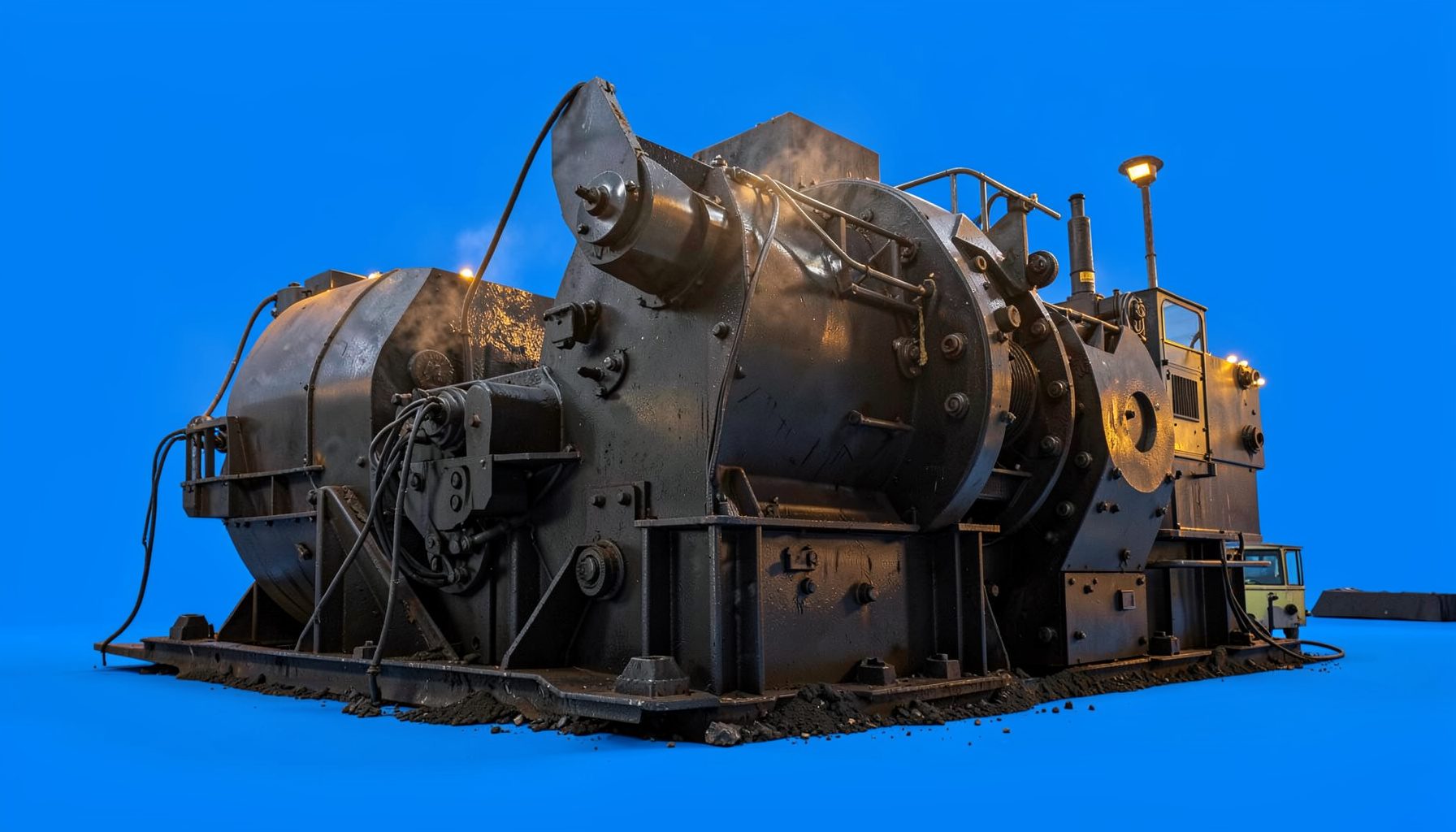
Why hydraulic relief systems protect cone crushers
Hydraulic relief systems are important for cone crusher protection because quarry feed is rarely uniform. A boulder, bridged fines pocket or slab can arrive between one truck and the next, forcing pressure in the crushing chamber to rise faster than the machine was designed to tolerate. The relief system provides a controlled pressure limit, helping protect the main shaft, bearings, crushing liners and hydraulic components from sudden overload. It does not make a poor setup safe, but it stands between a feed problem and a major mechanical failure.
A cone crusher relief circuit may include a pressure-control valve, directional valves, an accumulator and a return path to the hydraulic tank. When system pressure reaches the selected limit, the relief valve diverts oil so the crushing force can fall temporarily and the chamber has an opportunity to pass or settle a tramp object. Other circuits use the same hydraulic supply to change the closed side setting or release the cone. The exact arrangement varies by model, so the manufacturer’s manual must remain the authority for adjustment.
Australian sites make this protection particularly relevant. Cone crushers face hard Pilbara rock in Western Australia, variable coal and aggregate feed in the Hunter Valley, and high production expectations from mobile plant. Feed can change after rain, blending changes or a shift in the quarry. Sites also work in heat and dust, often with technicians travelling long distances, which makes preventive checks and suitable hydraulic oil especially important.
Shanghai CME Mining and Construction Machinery Co., Ltd. supplies cone crushers and mobile crushing plants alongside crushing, grinding, screening, washing and mineral-processing equipment. Its products are sold internationally, and product information and contact details are available from its Shanghai headquarters. For buyers and operators, that global perspective matters: protection is not an optional extra, but part of safe, economical crushing in demanding quarry and aggregate markets.
How the relief system absorbs overload
The crushing chamber creates extremely high mechanical forces. If steel, tramp iron or another uncrushable object becomes trapped between the mantle and the concave, hydraulic pressure can climb abruptly. A correctly functioning relief valve opens at its calibrated threshold and directs oil through the circuit’s safe return route. The chamber then loses some crushing force, reducing the shock transferred to the shaft and bearings instead of allowing the chamber to lock at full pressure.
Protection comes in stages. The valve may limit peak pressure, an accumulator may soften the initial shock, and a locking circuit may hold the setting when pump output falls. Each function must work together; a healthy relief valve cannot compensate for a damaged hose, contaminated oil or an accumulator with incorrect precharge. If the chamber remains overloaded after pressure is relieved, operators should stop and follow the site’s isolation procedure rather than repeatedly cycling the crusher against the obstruction.
Broader background on cone-crusher applications and supplier terminology is available in an equipment supplier overview, while the installed machine’s service manual should determine the actual relief setting. The value is not portable between makes, and an approved procedure is safer than copying a label from an old component. This distinction matters when a quarry combines machines of different ages or hydraulics suppliers.
What causes pressure spikes
Relief systems are commonly called upon after feed conditions change. Oversize material that misses the grizzly, a feed gap that is too small, worn crushing liners, a plugged feed conveyor or a build-up of fines can all raise chamber pressure. Incorrect hydraulic pressure and a failing accumulator can add to the load. The key is to identify whether the system has reached its limit because the chamber is genuinely overloaded or because a valve, line or sensor is not behaving as intended.
On Australian quarry operations, the loader and crusher form a mobile plant, so a truck delivering a different blend can alter the feed within minutes. In Pilbara hard-rock operations, occasional oversized fragments are common; in the Hunter Valley, coal moisture and fines handling can produce a different pressure pattern. Crews often call the crusher “the cone” and focus on getting the “plant running”, but that shorthand should not hide a rising pressure trend.
Warning signs include repeated relief-valve opening, pressure peaks above the logged limit, unstable setting, excessive cone bounce, unusual noise and fresh hydraulic leaks. A stoppage can also occur when an electrical fault prevents the pump or control circuit from operating. Panel fault guidance is a useful companion to hydraulic troubleshooting because electrical protection, earthing and pump control form part of the same safe isolation plan.
Setting the pressure correctly
The relief pressure is not a general-purpose adjustment. It must suit the crusher’s main shaft, bearing arrangement, hydraulic components and rated crushing force, so the value specified by the OEM should be used unless that manufacturer provides a documented site procedure. A setting that is too low can cause frequent valve opening, poor production and erratic product; one that is too high can transmit damaging force through the structure. Confirm the reading with a suitable gauge and verify oil viscosity at operating temperature.
Relief setting also interacts with chamber geometry, feed opening and closed side setting. A comparison of standard and short-head crushers explains how chamber design changes the crushing task and why settings from one machine should not be copied blindly to another. Operators should record the CSS in millimetres, feed rate in tonnes per hour and corresponding pressures, then make one controlled change at a time. That discipline is particularly useful when imported equipment operates in Australia under different feed moisture and duty conditions.
Commissioning should begin with clean fluid, correctly charged accumulators and warm hydraulic oil, followed by a controlled no-load check and gradual feed. Subsequent checks should compare trend data rather than relying only on an instantaneous gauge reading. When products vary, revisit feed distribution and screen performance before touching relief pressure. If the valve opens repeatedly at a stable feed, the machine needs investigation, not a higher pressure setting.
Maintenance and early diagnosis
Contamination is the enemy of hydraulic control. In dusty Pilbara conditions, a damaged hose or failed seal can introduce particles that make a relief valve stick; in wet Victorian or NSW aggregate plants, washdown water must be kept away from electrical and hydraulic connections. Maintenance should include fluid-level and condition checks, filter inspection, hose and fitting inspection, gauge comparison, tank-vent cleaning and verification of accumulator precharge where fitted. Follow the maker’s intervals and fluid specification.
Fault diagnosis becomes easier when symptoms are separated from causes. A circuit that never reaches relief pressure may have restricted feed, leakage, a weak pump or a failed control, so the relief valve can remain correctly closed. A valve that opens continuously can indicate a genuine chamber blockage, an undersized feed opening or leakage that prevents the circuit from building pressure. Trend the pressure, temperature and setting together, and inspect the hydraulic schematic before replacing parts.
Accurate records give technicians a reliable baseline, particularly where FIFO rosters and long travel distances make fault history hard to reconstruct. Controlled workshop copies of diagrams and service instructions can be kept as printed technical material, but they should match the current manual revision and never replace an authenticated OEM document. A laminated relief-setting card at the control station can help operators recognise the approved range without encouraging unauthorized changes.
Reliability across Australian quarry operations
For Australian operators, reliability depends on more than a correctly set valve. Local dealers or importers must be able to supply matched seals, filters, hose assemblies and valve components, while mine sites often keep critical spares because a technician may be days away. The market therefore rewards service packages, operator training and clear troubleshooting information alongside purchase price. On remote Pilbara and Hunter Valley sites, the maintenance program should fit production windows, hot weather and FIFO rosters instead of waiting for a visible failure.
Before a component is ordered, the serial number, model variant and hydraulic-fluid specification should be matched to the machine. An equipment reference library can help cross-check component names, while the crusher manual identifies the correct variant. This simple check reduces the chance of receiving an incompatible relief valve or accumulator, a common frustration when replacement parts move through local dealers and importers.
Useful fault comparisons connect observable signs with appropriate checks:
| Observed sign | Likely cause | Checks | Appropriate response |
|---|---|---|---|
| Pressure repeatedly reaches the limit | Oversize or bridged feed, CSS too small | Inspect grizzly, feed opening, CSS and chamber | Clear the obstruction under isolation and correct the feed or setting |
| Pressure never builds | Pump or electrical fault, leakage, failed control | Check power, pump output, leaks and circuit operation | Repair the supply or control fault and verify the approved setting |
| Cone setting drifts | Damaged seals, leakage or locking-circuit fault | Inspect seals, lines, clamps and accumulators | Restore the affected components and reset to the approved setting |
| Frequent opening with little production | Relief pressure too low or feed restricted | Verify the gauge, approved pressure and feed condition | Return the setting to specification after addressing feed restriction |
| Oil overheats, foams or leaks | Incorrect fluid, water ingress or air in the circuit | Check fluid level, specification, aeration and connections | Correct the fluid, remove air and repair water or oil ingress |
An effective protection strategy combines a machine-specific relief setting, clean hydraulic circuit, sound feed control and disciplined inspection. The relief system should be treated as a protective control within a safe system of work, not a licence to continue feeding an overloaded cone. Australian sites that preserve baseline data, train operators and maintain critical parts can contain a hydraulic fault before it becomes a bearing or shaft failure, reducing unplanned downtime while keeping the crushing circuit productive.