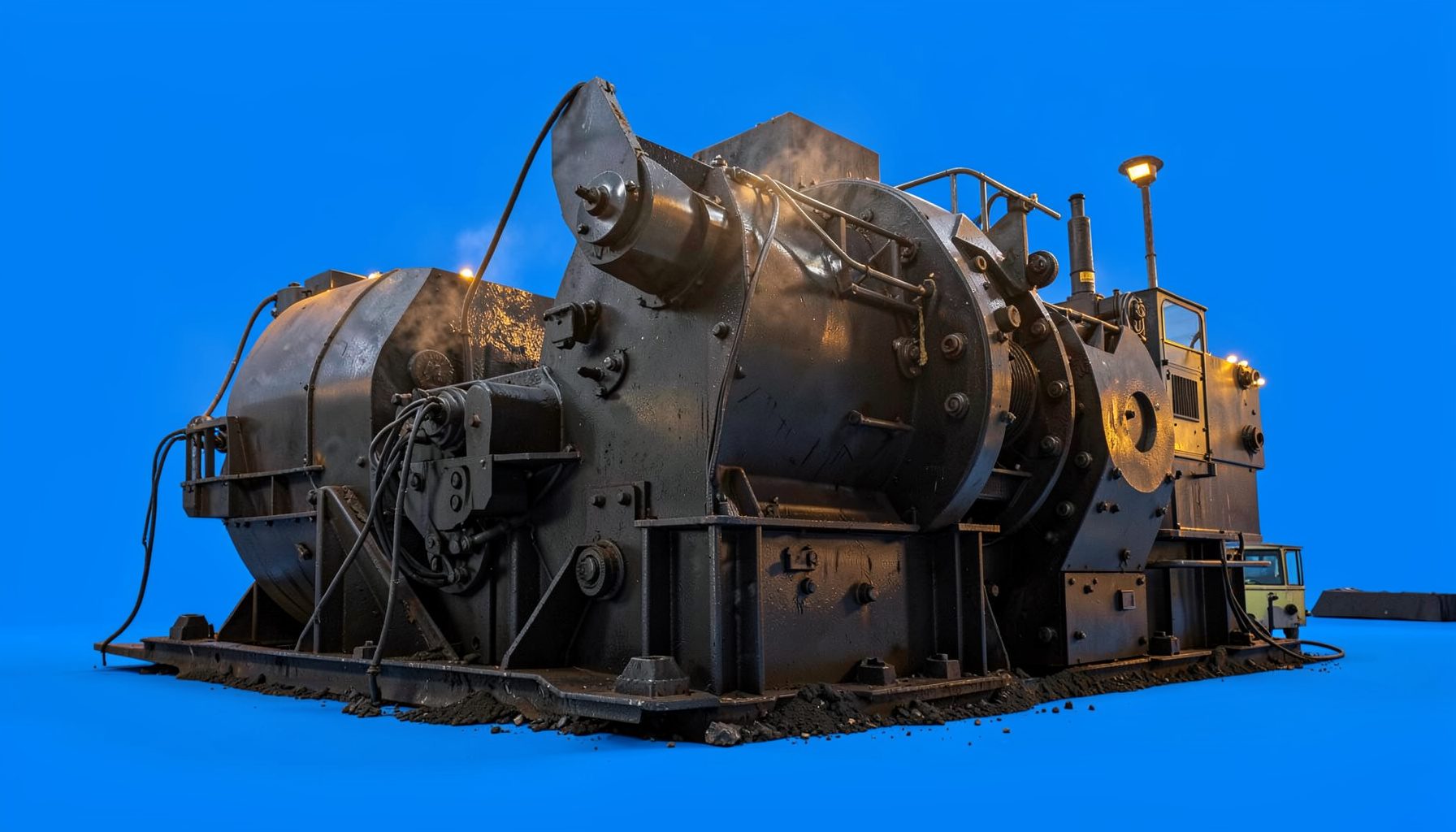
How to Troubleshoot Excess Flakiness In A Sand Making Machine
A sand making machine is expected to produce a controlled proportion of cubical particles for concrete, asphalt, manufactured sand and general construction aggregates. When the discharge contains too many flat, elongated or needle-shaped particles, the problem is usually linked to feed conditions, rotor configuration, crushing chamber wear or an unsuitable operating rate rather than one isolated component.
Excess flakiness can reduce compaction, increase binder demand and make it harder for a finished aggregate to meet project specifications. Australian quarry operators may also see the issue change between dry inland conditions and wet coastal weather, particularly when processing hard basalt, recycled concrete or variable alluvial material. A methodical inspection helps identify the cause before operators alter several settings at once.
Identify What Flakiness Means In The Product
Flaky aggregate has a small thickness compared with its length and width, while elongated material is significantly longer than it is wide. A particle may show either characteristic or both. The first step is to confirm the complaint with representative sampling rather than judging the product by appearance beside the conveyor.
Take samples from the final product at regular intervals and record the feed source, machine speed, closed-side setting of the preceding crusher, screen sizes and moisture condition. A laboratory or quarry quality team can then assess particle shape using the applicable project method. In Australia, specifications based on AS 2758.1 may impose requirements for aggregate shape, grading, durability and cleanliness, although the exact acceptance criteria depend on the application and contract.
Check whether the flakiness is present in the complete discharge or concentrated in one size fraction. If coarse particles are flat but manufactured sand is acceptable, the issue may be linked to oversize feed or inadequate secondary crushing. If the fine fraction contains excessive elongated chips, the rotor, anvils, cascade system or recirculating load deserves closer attention.
Check Feed Size, Grading And Material Condition
A vertical shaft impactor relies on controlled rock-on-rock or rock-on-metal impact. Feed that is too large, too coarse or poorly distributed through the rotor can strike the chamber unevenly and break along natural planes. Layered sedimentary rock, weathered material and fractured basalt may produce different shapes even when the machine settings remain unchanged.
Confirm that the maximum feed size stays within the manufacturer’s limit and that the feed is evenly spread across the rotor opening. A vibrating feeder should deliver a stable stream, rather than slugs of material followed by empty intervals. A surge bin with a properly adjusted level-control system can help prevent segregation and sudden loading. For mobile work around Perth, Newcastle or regional Queensland, uneven stockpiles and changing quarry faces can make feed variability especially pronounced.
Moisture can also affect the crushing chamber. Damp fines may build up around the feed eye, distributor or rotor, while sticky clay can coat surfaces and alter the material path. This reduces the impact efficiency available for shaping coarse particles. Remove clay contamination where practical, inspect for blockages during safe shutdowns and avoid compensating for wet feed solely by increasing rotor speed.
When the machine forms part of a portable circuit, review the complete arrangement rather than focusing only on the sand maker. Guidance on mobile crushing plants can help when checking whether feeder, crusher, screen and conveyor capacities are balanced. A screen overloaded by a sudden surge may return too much material to the impactor, creating a high circulating load and increasing the chance of repeated breakage.
Adjust Rotor Speed And Crushing Chamber Settings
Rotor speed is one of the strongest controls over product shape. Increasing speed raises impact energy and may improve cubicality when the feed is competent and the chamber is correctly configured. However, excessive speed can generate unnecessary fines, accelerate wear and cause some rocks to fracture into thin shards. Reducing speed slightly may improve the shape of a difficult feed, though an excessive reduction can leave more angular or poorly reduced particles.
Make one adjustment at a time and allow the circuit to reach a stable condition before sampling. Record the revolutions per minute, motor current, throughput and product grading for each trial. A sudden change in speed without monitoring the power draw can hide a developing blockage or allow the rotor to operate outside its efficient range.
Inspect the cascade or recirculation setting. A controlled cascade sends a portion of feed around the rotor to meet particles in the crushing chamber, often improving shaping while reducing metal-to-rock contact. Too much cascade can lower impact intensity and permit poorly shaped particles through; too little can increase direct impact, fines and wear. The correct balance depends on rock hardness, feed grading and the required sand specification.
| Observation | Likely Cause | Practical Check | Typical Response |
|---|---|---|---|
| Flat particles mainly in the coarse fraction | Oversize or slabby feed | Review scalping and feed-crusher settings | Improve pre-screening or secondary reduction |
| High flakiness with rising fines | Rotor speed or impact energy too high | Compare speed, amperage and grading | Reduce speed in small increments |
| Shape worsens after liner wear | Worn anvils, tips or chamber parts | Inspect wear profile during isolation | Replace or reverse components as permitted |
| Product changes during the shift | Unstable feed, moisture or segregation | Sample feed and discharge over time | Stabilise feeder rate and blend stockpiles |
| Poor shape with high circulating load | Screen efficiency or setting problem | Check screen media, loading and returns | Correct screening and reduce recirculation |
| Flat particles across every size | Unsuitable rock texture or machine selection | Compare lithology and test results | Review process design or equipment choice |
A comparison with other crushing stages can prevent incorrect adjustments. The operating principles of gyratory and cone crushers differ from those of a vertical shaft impactor, so settings that produce a good result in a cone circuit cannot be transferred directly to a sand-making machine. The VSI should be treated as a shaping stage with its own feed, speed and wear requirements.
Inspect Wear Parts And Product Classification
Worn rotor tips, distributor plates, anvils, feed tubes and cavity liners change the trajectory and impact point of the rock. Uneven wear is particularly important because it can make one side of the chamber process more aggressively than the other. This may result in inconsistent particle shape, vibration, unusual power consumption and a gradual rise in flakiness.
Follow the site isolation procedure before opening inspection doors or entering the crushing area. Look for rounded tips, cracks, missing hard-facing, uneven anvil faces and material build-up. Check rotor balance, bearing condition and the clearance between key components. A damaged rotor or loose wear part should be repaired according to the equipment manufacturer’s instructions rather than corrected by a larger speed change.
The screening circuit often determines whether the shape problem becomes visible in the saleable product. Worn screen media, incorrect aperture selection or excessive deck loading can send oversized, flat particles into the final product or return an abnormal quantity to the sand maker. Inspect tension, blinding, pegging and spray-bar performance on wet screens. Recycled water systems used at Australian sites should also be checked for excessive clay or suspended solids that may reduce classification efficiency.
Product specification should guide every adjustment. A quarry supplying concrete aggregate near Melbourne may require a different grading and shape profile from a producer making asphalt aggregate near Sydney or manufactured sand for a regional road project. Keep retained samples from accepted production runs so that operators can compare new material against a known benchmark instead of relying on visual judgement alone.
Build A Controlled Troubleshooting Routine
Begin with the simplest checks: verify the feed rate, measure moisture, inspect the feed size and confirm that the correct rotor and chamber configuration is installed. Then review the machine’s speed, motor load, cascade setting and discharge grading. Changes to several variables at once make it difficult to identify the factor that actually improved or worsened the product.
Use a short trial protocol. Establish a baseline sample, adjust one setting within the manufacturer’s operating range, run long enough to clear the previous material, and collect a second representative sample. Record flakiness, fines percentage, throughput, energy use and any signs of vibration or temperature rise. Repeat only when the results are stable. This approach is useful in both fixed plants and mobile circuits that move between deposits.
Good housekeeping supports reliable shape control. Keep the feeder, transfer points and screen decks free from build-up, maintain accurate belt scales and inspect conveyors for spillage that can contaminate samples. Tool selection matters during routine service: properly maintained professional power tools can assist with approved maintenance tasks, but guards, isolation systems and site safety procedures remain essential around rotating machinery.
Australian operating conditions deserve particular attention. Summer heat in inland New South Wales can affect bearing temperatures and lubrication intervals, while wet seasons in northern Queensland may increase clay carryover and feed moisture. Coastal quarries can face salt-laden air and heavy rain, and water restrictions may influence washing and dust-control arrangements. Schedule inspections around production demands, keep critical wear parts available and train operators to recognise changes in vibration, sound, amperage and product texture.
If feed, speed, wear and screening checks do not resolve the issue, assess the broader process design. The rock may have a natural plate-like structure that limits the achievable shape, or the machine may be undersized for the required reduction ratio. A process audit, laboratory shape analysis and trial using a different chamber configuration can establish whether the remedy is operational, mechanical or related to equipment selection. Consistent sampling and documented adjustments will then provide a defensible basis for producing stable, specification-compliant aggregate.