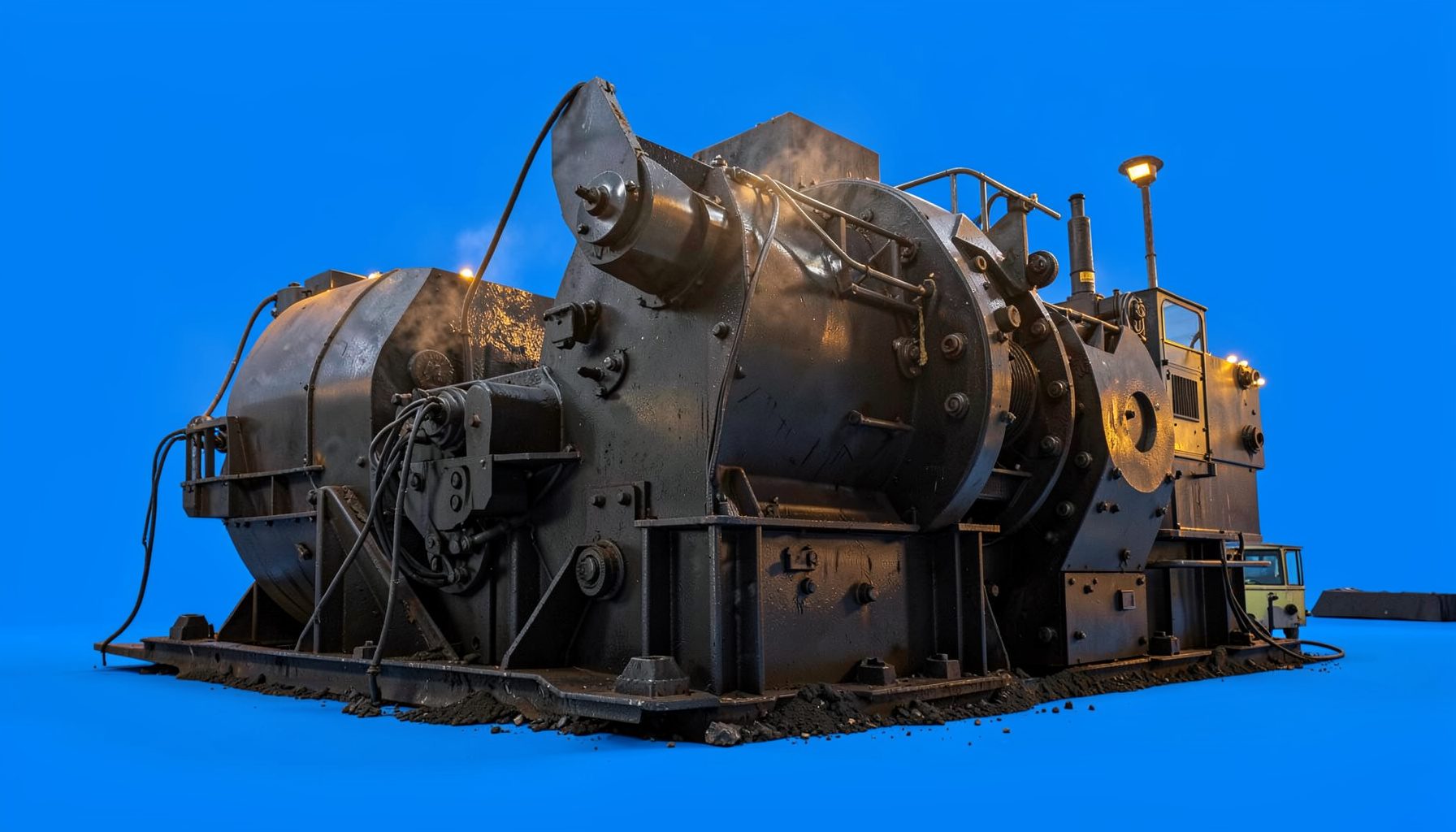
Choosing Cone Crusher Feed Size for Reliable Crushing
The feed size entering a cone crusher has a direct effect on capacity, product shape, liner life and power draw. A rock that is too large for the selected chamber can bridge across the crushing cavity, restrict material flow and force the machine to work under unstable load. The result may be a trip, damaged components or a gradual loss of throughput rather than an obvious single failure. Learn more about Grinding Equipment.
There is no universal maximum lump size that suits every cone crusher. The correct limit depends on the feed opening, chamber profile, closed-side setting (CSS), rock characteristics and the reduction ratio required. In practice, operators should work from the manufacturer’s rated top-size guidance and keep a sensible margin below the nominal opening, particularly when feed is blasted rock with irregular slabs.
Read the Feed Opening Correctly
A cone crusher’s feed opening is the largest practical entry point at the top of the crushing chamber. It is not a target dimension for every piece of rock. A nominal opening of 200 mm does not mean that a continuous stream of 200 mm, sharp-edged lumps will pass safely and evenly. Shape, moisture, fines and the position of the rock as it enters all affect whether it feeds freely.
For coarse crushing duties, a common operating rule is to keep the maximum feed at roughly 80% of the stated feed opening. Some applications may permit a higher percentage under carefully controlled conditions, while finer chambers generally require a smaller top size. The exact figure must come from the crusher’s technical data because manufacturers define feed limits differently.
The purpose of this allowance is to prevent bridging and maintain a steady bed of material around the mantle. A rock that barely fits may rotate into a favourable position, but another piece of the same measured size may lodge across the cavity. Oversize should therefore be measured by its longest practical dimension, not by assuming that a flat or elongated fragment behaves like a cube.
Match Top Size With the Crushing Chamber
Cone crushers use different chamber profiles for coarse, medium, fine and extra-fine applications. A coarse chamber has a larger receiving area and is normally selected when the machine must accept larger run-of-mine or primary-crushed material. A fine chamber has a smaller entry zone and relies on a controlled feed to produce a tighter product.
The closed-side setting is equally important. CSS is the smallest gap between the mantle and concave during the crushing cycle, and it governs the product’s lower size range. It does not describe the maximum feed size. If the feed is too large compared with the CSS, the crusher may be forced into an excessive reduction ratio, increasing pressure, recirculation and power demand.
A useful design check is the reduction ratio: feed top size divided by the desired product top size. When this ratio becomes too aggressive for one crushing stage, reducing the feed alone may not solve the issue. A primary jaw crusher, impact crusher or an additional cone stage may be needed. Information about crushing equipment can help place the cone within a broader size-reduction circuit rather than treating it as a standalone machine.
Account for Rock and Feed Conditions
Hardness is only one part of the feed equation. Abrasive quartzite, basalt and iron-rich ore can consume liners quickly and draw high power even when the lump size is within the stated limit. Tough, slabby rock can create bridging, while friable material may break readily but generate excess fines that choke the chamber or reduce screening efficiency.
Moisture and clay can be just as troublesome. Damp fines may coat the chamber, blind the screen or form a sticky layer on the feeder. This changes the way coarse particles enter the cavity and can create surges in load. For quarry feed containing clay bands, scalping before the cone is often more effective than simply choosing a larger crusher.
Feed gradation should be considered alongside maximum size. A narrow stream made almost entirely of large rocks is harder on a cone than a well-graded feed containing smaller particles that support continuous interparticle crushing. A controlled mixture can improve throughput, but excessive fines can reduce air space and raise the risk of packing. Moisture, bulk density and abrasiveness should be included in the process review.
Compare Practical Feed Ranges
The following values are planning ranges, not replacements for the crusher manual. They illustrate how the same nominal machine opening can require different feed limits according to chamber duty and material behaviour.
| Operating situation | Practical maximum feed approach | Main overload risk | Useful control |
|---|---|---|---|
| Coarse chamber, clean hard rock | About 75–85% of feed opening | Bridging from angular lumps | Scalping and steady feeder speed |
| Medium chamber, well-graded quarry feed | About 65–80% of feed opening | High pressure from excessive reduction | Maintain correct CSS and choke level |
| Fine chamber, screened feed | About 50–70% of feed opening | Packing and power spikes | Tight control of top size and fines |
| Wet or clay-bound feed | Below the normal percentage where necessary | Coating, plugging and uneven flow | Washing, scalping or moisture management |
| Slabby blasted rock | Conservative limit below nominal guidance | Crosswise bridging at the feed zone | Secondary breaking or improved blasting |
These ranges show why a simple “maximum millimetres” answer can be misleading. A 150 mm rounded cobble may feed more easily than a 120 mm flat slab. Likewise, a dry, clean aggregate stream can perform well at a size that would be unsafe in sticky clay. Operators should start conservatively, monitor the machine and adjust only within the manufacturer’s permitted operating envelope.
A cone should also be protected from sudden surges. The feeder, transfer chute and upstream screen need enough capacity to deliver a consistent stream rather than intermittent batches. Surge bins and level sensors can help separate the irregular output of a loader or primary crusher from the steady feed rate required by the cone.
Recognise Overload Before Damage Occurs
The most visible overload symptom is a sharp rise in motor current or hydraulic pressure. However, overload can develop gradually. Throughput may decline, the crusher may begin to ring or bump, discharge may become inconsistent and the product may contain more oversize than usual. Repeated tramp-release events are another warning that unwanted large objects or uncrushable material are entering the chamber.
A cone crusher operating correctly usually maintains a relatively stable power draw under a full, even feed. Empty running followed by heavy surges is undesirable because the crushing cavity alternates between starvation and excessive loading. A choke-fed condition, where the chamber remains consistently filled to the level specified by the manufacturer, generally supports better particle shape and more efficient crushing.
Measurement makes diagnosis more reliable. Belt scales, motor-current trends, hydraulic pressure readings and CSS checks can reveal whether the real problem is oversize, a blocked screen, worn liners or an incorrect feeder setting. Industrial precision instruments are useful when a quarry needs repeatable load and flow data rather than relying solely on visual inspection.
Adapt the Setup to Australian Quarries
Australian quarry conditions vary widely. A hard basalt operation near Melbourne, for example, may prioritise wear resistance and power management, while a sandstone or recycled aggregate site around Brisbane may have very different feed behaviour. In Western Australia, remote iron ore and mineral-processing sites often place extra value on robust automation, spare-parts planning and clear alarm data because unplanned shutdowns can involve long service delays.
The country’s dry conditions can create dust around feeders and transfer points, while sudden rain can turn fines into sticky material. In regional New South Wales or Queensland, a quarry may switch between blasted rock, scalped feed and recycled concrete depending on local contracts. Terms such as “crusher dust,” “road base” and “oversize” are common in site conversations, but each operation should still define sizes precisely in millimetres and confirm them with screen analysis.
Australian projects also work within practical production constraints. Haul distances, strict noise and dust controls, quarry licences and the need to supply road aggregate consistently can make a stable feed more valuable than a short-term peak rate. Mobile crushing plants may move between benches or construction sites, so compact transfer arrangements and quick CSS changes can matter as much as maximum theoretical capacity.
Build Feed Control Into the Plant
Correct feed sizing starts before the cone. Blasting should aim for a manageable fragmentation profile, and a primary jaw or gyratory crusher should produce a top size suited to the secondary cone. A vibrating grizzly or scalping screen can remove fine material that does not need to pass through the chamber, reducing unnecessary power use and improving the effective capacity of the crusher.
The conveyor and chute design must prevent segregation. If large rocks roll to one side while fines collect on the other, the cone receives an uneven feed even when the belt appears full. A properly centred transfer, adequate chute angle and controlled belt speed help distribute material across the crushing cavity. For a complete circuit, complete plants provide useful context on how feeders, crushers, screens and conveyors are arranged as one process.
The cone’s discharge must also be considered. If the downstream screen cannot clear the product, material returns through the recirculating load and the cone sees more work than expected. A rising circulating load may indicate that the CSS is too tight, the feed is too coarse for the selected chamber, or the screen aperture and deck arrangement need attention.
Use a Repeatable Sizing Procedure
Begin by recording the feed opening, chamber type, recommended CSS range and allowable top size from the equipment manual. Then measure the actual feed with a proper sample rather than relying on loader bucket estimates. Record the percentage passing the target top size, the largest individual pieces, moisture condition, bulk density and any clay or tramp content.
Next, match the measured feed with the desired product and capacity. If the maximum lump is too close to the crusher’s limit, use secondary breaking, better blasting, a scalper or a different chamber. Do not solve an oversize problem by repeatedly increasing CSS, because that can compromise product specification and may simply move the bottleneck downstream.
During commissioning, increase feed gradually while watching motor load, hydraulic pressure, chamber level, belt scale rate and product gradation. Keep a written record of changes to feeder speed, CSS and liner condition. After liner wear changes the chamber geometry, reassess the feed behaviour rather than assuming the original settings remain suitable.
The ideal feed is therefore a controlled, well-graded stream with a top size comfortably below the chamber’s rated entry limit. With accurate measurement, suitable upstream sizing and steady feeding, a cone crusher can operate near its designed capacity without the pressure spikes and interruptions associated with oversize rock.