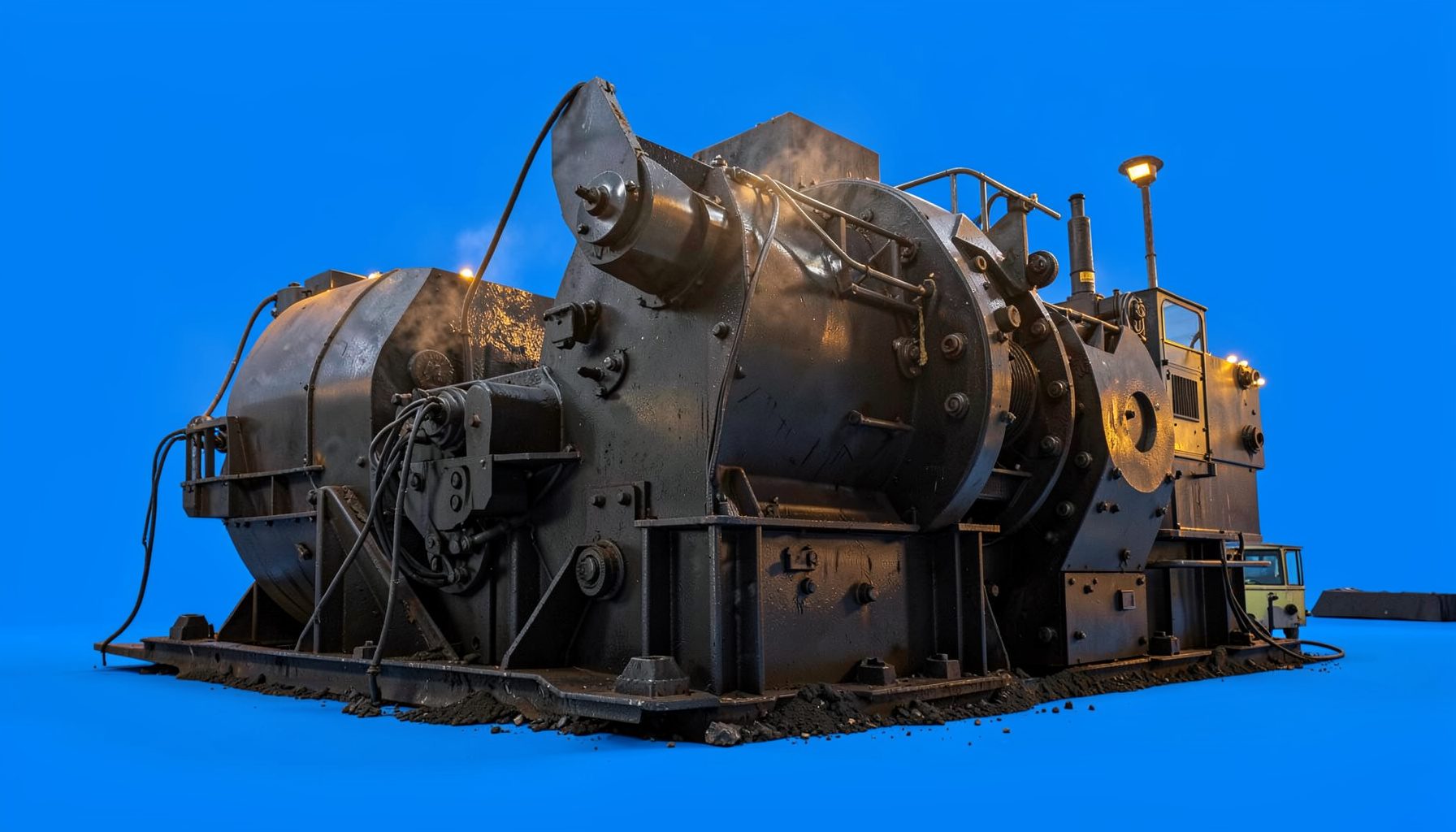
Sizing a Surge Bin for Consistent Crusher Feed
A surge bin provides controlled storage between stages of a crushing circuit. It absorbs short-term differences between the upstream feed source and the downstream crusher, helping the crusher receive a steady flow rather than alternating between starvation and overload. Correct sizing therefore affects capacity, product shape, liner wear, energy use, and the reliability of the complete plant.
The right design starts with the material and operating duty, not with a standard bin volume. Feed rate, bulk density, moisture, top size, segregation, particle shape, and the required buffer time all influence the result. A bin that appears large on a drawing may have a much smaller usable capacity if material bridges above the outlet or forms a stagnant zone.
For Australian quarry and mining operations, the design also has to suit remote maintenance, variable weather, strict guarding requirements, and long shifts. A surge bin feeding a cone crusher near Newcastle, a hard-rock circuit outside Brisbane, or an iron ore plant in the Pilbara will face different risks and operating priorities. A sound calculation should reflect the actual site rather than a nominal equipment catalogue value.
Define The Operating Duty
Begin by identifying the material flow entering and leaving the bin. The upstream rate may come from a jaw crusher, apron feeder, mobile crushing plant, or truck-fed hopper. The downstream requirement is usually the crusher’s desired continuous feed rate. These figures should be expressed on the same basis, preferably tonnes per hour and dry or wet condition clearly stated.
A useful first calculation is the required live mass:
Live mass capacity = net feed rate × required buffer time
If a secondary cone crusher requires 250 tonnes per hour and the bin must provide 12 minutes of live surge, the starting requirement is 50 tonnes. This is the mass that must be reliably extracted through the outlet, rather than the total material contained in every corner of the vessel.
Buffer time depends on the cause of the interruption. A short pause caused by a belt-metal detector may require only a few minutes. A truck exchange, screen inspection, or upstream crusher reset may require a longer reserve. If the bin is expected to keep the plant operating while a primary unit stops, its capacity must be based on that event rather than on ordinary fluctuations.
The design should also distinguish average rate from peak rate. A feeder may deliver 300 tonnes per hour for part of a cycle even though the daily average is 220 tonnes per hour. The bin, feeder, conveyor, and crusher must be checked against the peak duty. A reliable process model typically includes start-up, shutdown, blocked chute recovery, planned maintenance, and variations in truck arrival or blasting schedules.
Convert Mass Into Usable Volume
Mass capacity must be converted into volume using the loose bulk density of the material in the bin. This is not the same as laboratory particle density or the solid density of the mineral. Crushed rock contains voids, and the void ratio changes with grading, moisture, compaction, and vibration.
The basic relationship is:
Required live volume = required live mass ÷ loose bulk density
For 50 tonnes of live capacity at a loose bulk density of 1.6 tonnes per cubic metre, the theoretical live volume is 31.25 cubic metres. The final geometric volume will be greater because the bin cannot be emptied completely, the outlet needs a safe operating head, and the upper section may not discharge uniformly.
A practical calculation can be represented as:
Total geometric volume = live volume ÷ usable-volume factor
The usable-volume factor accounts for dead zones, retained material, level-control limits, and the fact that the bin is not operated from completely full to completely empty. Depending on the geometry and material, a preliminary factor might range from 0.65 to 0.85, but it should be confirmed through flow testing, discrete element modelling, or experience with comparable material. Selecting a factor without checking the flow pattern can create a serious under-design.
Material density should be measured across the expected range. Freshly blasted basalt from a Queensland quarry may behave differently from recycled concrete, damp limestone, or magnetite-bearing ore. A wet-season feed from a site near Darwin can carry more clay and moisture than the same face during the dry season. These changes affect both mass-to-volume conversion and discharge behaviour.
Match Geometry To Material Flow
Bin shape is as important as capacity. A steep mass-flow hopper encourages older material to move first, reducing stagnant regions and limiting segregation. A central outlet can work well for uniform material, while an offset outlet may require careful geometry and flow analysis to prevent one side of the bin from retaining material.
The outlet must be large enough to prevent arching, rat-holing, and bridging. A crusher feed containing large flat particles, clay, or wet fines can need a wider opening than a dry, well-graded aggregate. The feeder beneath the bin should withdraw material across the full outlet area. A narrow belt feeder or poorly matched vibrating feeder can create a preferential flow channel even when the upper bin is correctly sized.
The table below shows how the main design variables affect the calculation and equipment selection.
| Design variable | Why it matters | Typical design response |
|---|---|---|
| Net crusher feed rate | Establishes the required tonnes per hour | Size live capacity from the sustained downstream demand |
| Buffer duration | Determines how long the crusher can run during an interruption | Use a measured or agreed event duration, not an arbitrary volume |
| Loose bulk density | Converts stored tonnes into cubic metres | Test representative material at expected moisture levels |
| Top size and shape | Influences bridging, impact loading, and outlet dimensions | Check lump size against hopper opening and feeder design |
| Moisture and clay | Increases adhesion and may cause hang-ups | Use liners, steeper walls, air cannons, or flow aids where justified |
| Flow pattern | Controls dead zones and segregation | Prefer mass flow or validate funnel flow with modelling and trials |
| Feeder withdrawal rate | Sets the actual discharge from the bin | Match feeder capacity, speed control, and crusher demand |
| Level instrumentation | Prevents high-level blockage and low-level starvation | Use reliable level switches, radar, load cells, or belt scales |
Accurate measurement is especially valuable during commissioning. Load cells, belt scales, and level instruments can verify whether the bin is maintaining the intended reserve. Suppliers such as Cavendish Instruments can be considered when reviewing industrial weighing and measurement equipment for this part of the circuit.
Select The Feeder And Control Strategy
A surge bin only performs its job when the extraction system is coordinated with the crusher. The feeder should provide a stable, adjustable rate over the full operating range. A belt feeder is often suitable for high capacity and controlled withdrawal, while a vibrating feeder may suit free-flowing material and compact layouts. Apron feeders are useful where the bin receives severe impact or large, coarse rock.
The feeder should be selected for both normal and upset conditions. Its maximum capacity needs to clear the bin safely without exceeding the crusher’s allowable feed rate. Conversely, its minimum controllable rate must be low enough to prevent the crusher from starving when upstream supply is reduced. Variable-frequency drives and a crusher power or chamber-level signal can help regulate the flow.
A typical control sequence uses a high-level alarm to slow or stop the upstream equipment, a low-level alarm to reduce the crusher rate or stop it safely, and an operating level signal to adjust feeder speed. Interlocks should prevent the upstream crusher from continuing to fill a bin when the downstream conveyor is stopped. High-high level protection is important because a full bin can impose major loads on liners, gates, and supporting steelwork.
Instrumentation needs protection from impact, dust, vibration, and build-up. A radar level sensor may perform well in one application, while load cells or multiple point switches may be more dependable in another. The control philosophy should be tested with empty, normal, wet, and partially blocked conditions. Operators on Australian mine sites commonly work with long travel distances and shift handovers, so alarms need to be clear, prioritised, and visible from the control room and local operating area.
Allow For Site Conditions And Safety
Structural design must include the weight of the stored material, impact from incoming rock, dynamic feeder loads, wind, seismic effects where applicable, and maintenance loading. The maximum retained mass can be considerably higher than the mass associated with normal operating level. Support legs, transfer towers, chutes, and foundations should be checked as one load path.
Access and maintenance deserve early attention. Replaceable wear liners should be installable without excessive confined-space entry. Inspection doors need safe platforms, adequate lighting, and isolation procedures. Guarding around the feeder, drive, pulleys, and discharge chute must be integrated into the layout rather than added after construction. Australian projects should align the risk assessment and guarding approach with applicable workplace machinery safety requirements, including the AS 4024 series where relevant.
Dust suppression and weather protection may influence the bin roof and outlet design. In dry inland regions, enclosed transfer points and dust extraction can be essential. In northern Australia, heavy rain can change the flowability of fines and increase the risk of material build-up. Coastal sites around Perth or Adelaide may require suitable corrosion protection, while a remote Pilbara installation may prioritise robust components, simple access, and readily available wear parts.
Space and transport constraints are also practical design limits. A large fixed bin may be economical for a long-life quarry outside Sydney, but a relocatable operation may need a modular hopper that can be moved with the rest of a mobile circuit. Reviewing mobile plant options can help frame the differences between fixed surge storage and transportable crushing arrangements, even though the final selection must reflect the Australian site, road rules, and production duty.
Verify Capacity Before Installation
A calculation should be checked against the complete circuit balance. Confirm that the upstream crusher can refill the bin at the required rate, the feeder can extract material smoothly, and the downstream crusher can accept the maximum possible flow. A large surge bin cannot compensate for a feeder that is too small or a transfer chute that repeatedly plugs.
Flow testing with representative material is valuable where the feed contains clay, wet fines, elongated rock, or a wide top-size range. Testing can reveal segregation, impact damage, liner wear, and retained pockets that a simple volume calculation misses. Discrete element modelling may be justified for high-capacity iron ore, expensive shutdowns, or unusual hopper geometry.
Commissioning should include a measured inventory test. Record feeder rate, crusher power, bin level, material density, and the time taken to move between agreed operating levels. Comparing these values with the design model provides a practical correction to the usable-volume factor. It also identifies whether the level instrument is reporting actual inventory or only a local surface condition.
The final equipment package may include the bin, feeder, liners, level controls, dust suppression, structural supports, transfer chutes, and maintenance platforms. A broader review of crushing equipment range can provide useful context when coordinating the surge bin with jaw, cone, impact, screening, and conveying equipment. The finished design should leave a clear operating margin without creating unnecessary stored mass, structural cost, or residence time.
Correct sizing is therefore a balance between process continuity and material flow behaviour. Calculate the live tonnes from the real interruption duty, convert them using tested bulk density, allow for unusable volume, and verify the hopper, outlet, feeder, controls, and structure as a single system. That approach gives a crusher a steadier feed and gives operators a circuit that is easier to control, inspect, and maintain.